A bellows expansion joint works through the controlled deformation of its flexible element. However, its suitability is not determined by the movement range given in the catalogue alone. Bellows geometry, pressure, temperature, the number of cycles and the way the pipeline is guided form a single load system that has to be considered as a whole.
We describe expansion joint movement relative to the installed position
When a heated section of pipeline expands, an axial expansion joint between anchors may be compressed. In the documentation, movement should therefore be described from the perspective of the expansion joint ends: as compression, extension, lateral offset or a change of angle relative to the installed position. This approach removes the ambiguity that often arises with terms such as “pipeline elongation”.
Axial movement
It changes the distance between the connections along the pipeline axis. Compression and extension should be stated separately, because the installed position is not always in the middle of the full permissible working range.
Lateral movement
It shifts one end of the assembly relative to the other in a direction perpendicular to the axis. In addition to the offset value, its plane and the overall length of the assembly matter. For larger lateral movements, double-bellows arrangements are among the solutions used.
Angular movement
It changes the angle between the axes of the expansion joint ends. Angular deflection is considered as part of the geometry of the entire piping system, especially when several expansion joints work together as a hinged system.
Twisting about the pipeline axis is not another type of angular movement. For metal bellows, it is a load that should be avoided in the design and during installation.
Combined movements are not the sum of independent catalogue maxima
In an installation, axial, lateral and angular movement can occur in the same operating state. If the expansion joint is compressed and offset laterally at the same time during start-up, both displacements form a single load case. It cannot be assumed that the maximum axial movement, the maximum lateral movement and the maximum angular deflection are available simultaneously.
The range of combined movements results from the characteristics of the specific bellows and the pressure loads. That is why selection requires the actual combinations of displacements occurring in successive operating states, not just the largest values recorded separately for each axis.
When a double-bellows design is used
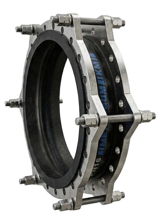
Where a larger lateral offset is required, one of the solutions is two bellows connected by a pipe section. The lateral displacement is then produced by opposite angular deflections of the two bellows. The available movement range depends on the bellows spacing, their geometry, the permissible deflection and the way pressure forces are restrained.
In such an assembly, what matters is not only the offset of the ends but also how the movement is divided between the two bellows. Control elements can stabilise the system and enforce the correct distribution of displacements, but they should not be confused with elements that restrain the pressure thrust.
Multi-ply bellows: flexibility, pressure and service life
In a multi-ply bellows, the wall of the flexible element is made of several thin layers of metal. This makes it possible to achieve different elastic characteristics than with a single-ply wall and to design the assembly for the required movement range, pressure and cyclic loads.
The number of plies alone does not determine the service life of an expansion joint. The design has to take into account the stress range resulting from movement, the temperature, pressure, material, convolution geometry and the number of cycles. Where vibration is present, the frequency and amplitude of the excitation and the assembly’s own dynamic characteristics also come into play.
The spring rate of the bellows is also important. The greater the reaction force needed to achieve a given displacement, the greater the load that may be transferred to equipment nozzles, supports and other pipeline components.
Pressure thrust, anchors and the function of tie rods
Pressure acting on the effective area of the bellows generates an axial pressure thrust. If the expansion joint assembly has no structure that restrains this force, it must be taken up by properly designed anchors in the installation. Guides maintain the direction of pipeline movement, but they do not replace an anchor capable of absorbing axial loads.
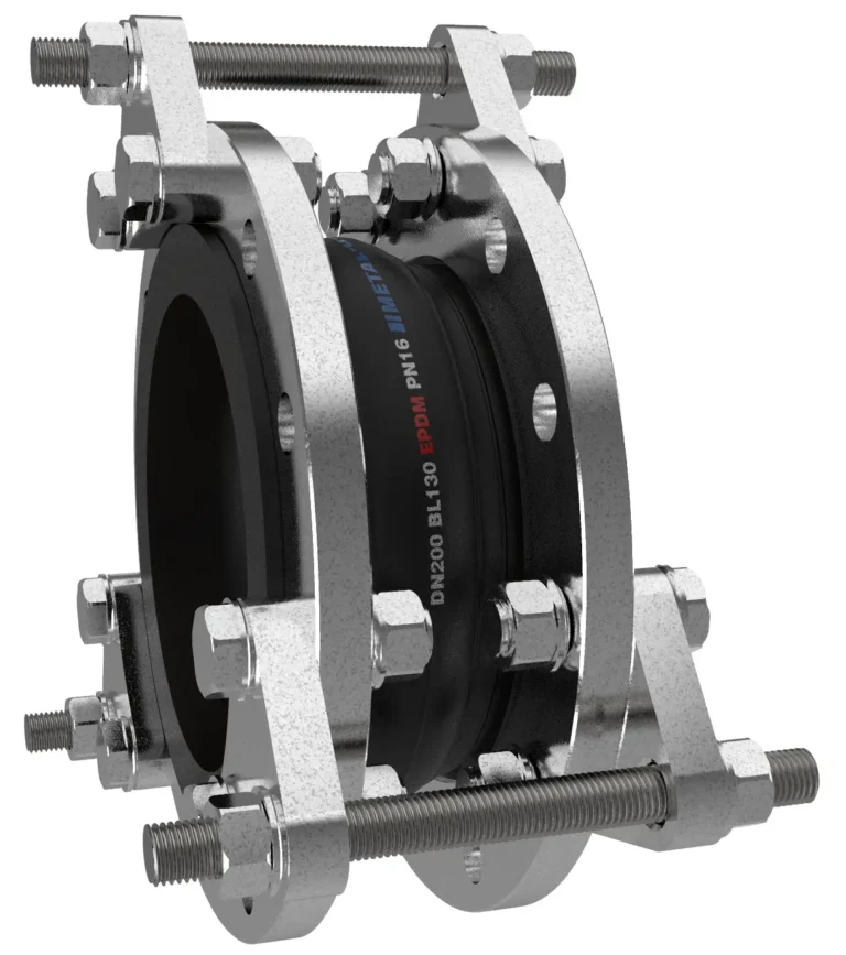
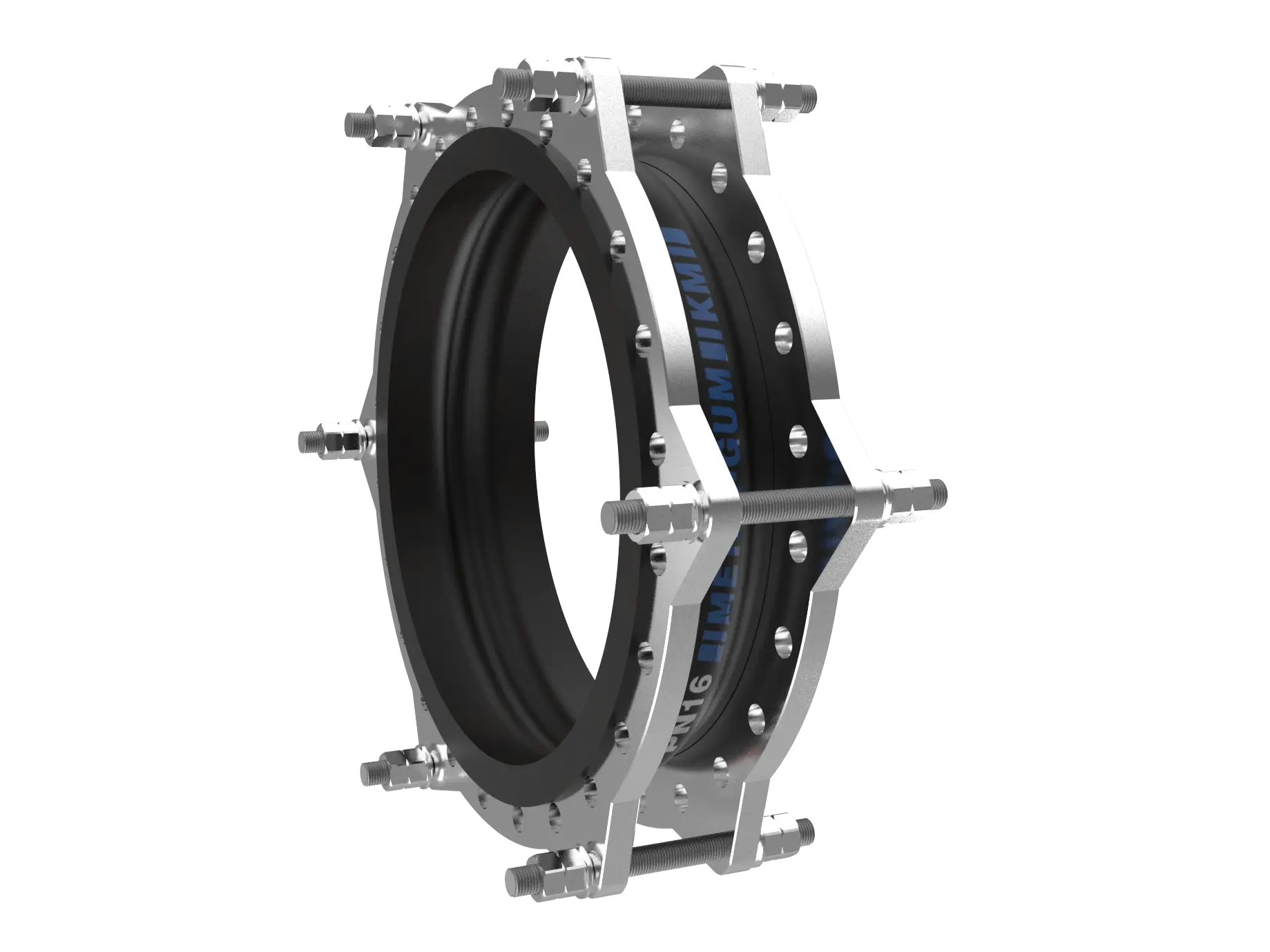
Rods fitted to an expansion joint can perform different functions and should not be judged by their appearance alone:
- tie rods that restrain the pressure thrust limit the free axial movement of the assembly;
- limit rods set the permissible end positions and protect the bellows from exceeding the design range;
- control elements in a double-bellows design are used to control the geometry and the division of movement between the bellows.
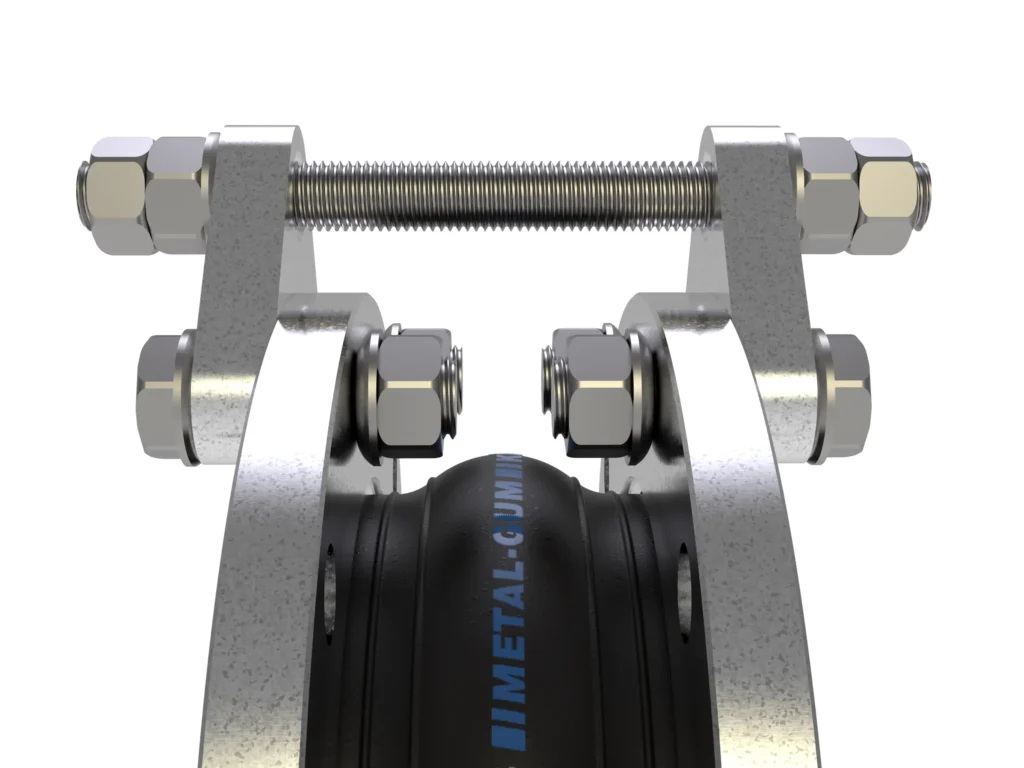
The function of these elements must follow from the documentation of the specific assembly. A similar external geometry does not mean an identical way of working.
What data is needed to select a bellows expansion joint
A good specification describes the expansion joint as part of the entire piping system. Selection requires, above all:
- a pipeline diagram showing anchors, guides, supports and equipment connections;
- the available installation length and the installed position of the expansion joint;
- the movements of the expansion joint ends relative to the installed position, indicating the components that occur simultaneously;
- the medium, pressure and temperature for normal operation, start-up, shutdown and other relevant process states;
- the number of cycles and the nature of any vibration;
- DN, the connection type, the required materials and additional equipment;
- the permissible forces and moments on the nozzles of connected equipment;
- when replacing an existing assembly – a drawing, dimensions, documentation and a description of the reason for replacement or of the damage.
Installation should not use up the working range of the bellows
An expansion joint is not a component for correcting an accidental error in flange spacing. Forced extension, compression or lateral offset during installation introduces a pre-deformation that is later superimposed on the working movement of the installation. A similar problem arises when the ends of the assembly are rotated to align the bolt holes, because this can introduce torsion into the bellows.
If the design provides for a controlled pre-deformation, it should follow from the documentation of the specific expansion joint and the calculated working range. This is a completely different situation from improvised “pulling” of the component to fit a misaligned installation.
Metal bellows, rubber and PTFE require separate assessment
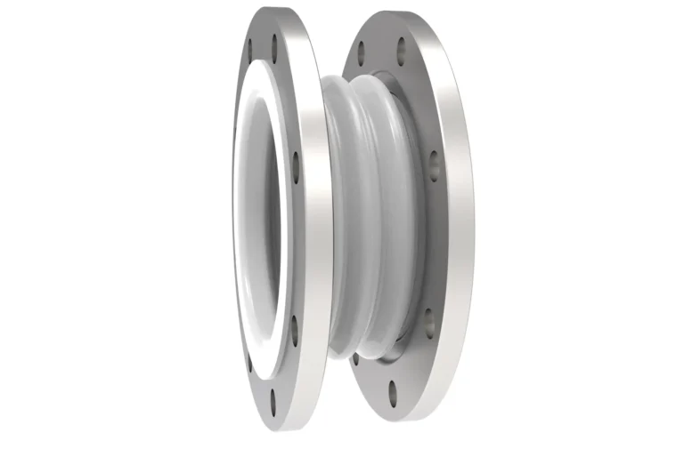
The relationships used in designing a metal bellows do not transfer directly to rubber expansion joints or PTFE expansion joints. In a rubber design, the behaviour of the flexible element depends on factors including the elastomer compound, the reinforcement and the arch geometry. In PTFE, the properties of the fluoropolymer, the bellows geometry and the dependence of the permissible parameters on temperature and pressure are important.
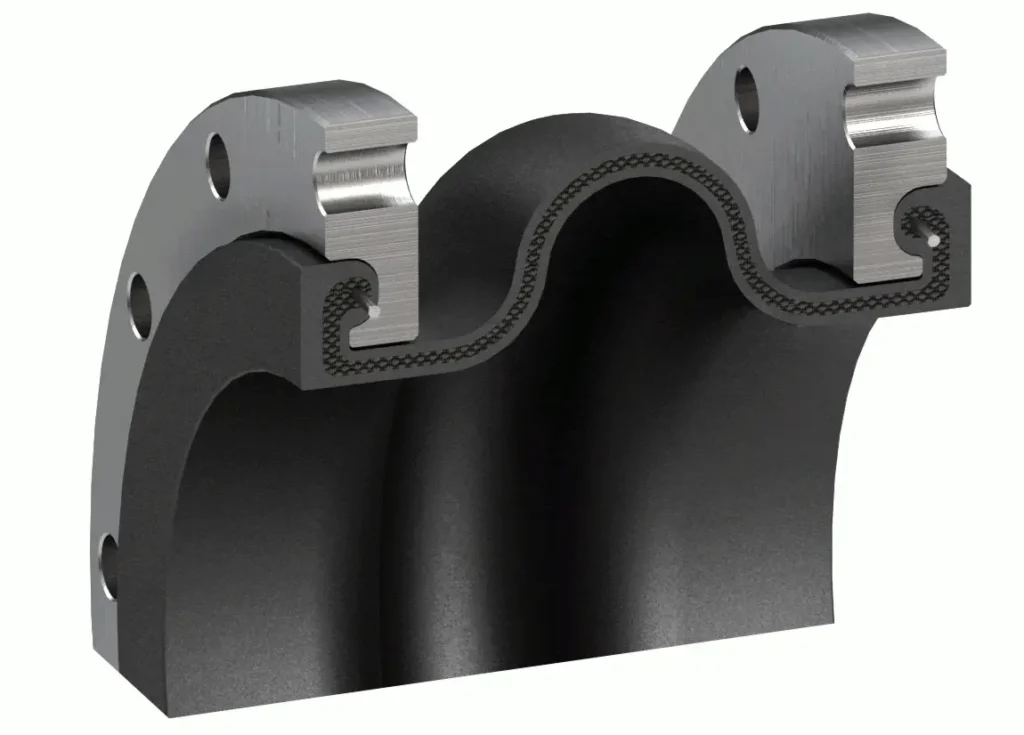
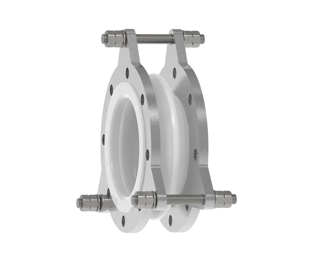
At Metal-Gum, we select rubber and PTFE expansion joints for the actual conditions of the installation: the medium, temperature, pressure, required movements and installation method. If the movements are combined, the technical discussion should be based on a pipeline diagram showing their values and directions and the locations of anchors and guides.
Questions about installation and design
Can a bellows be used to correct incorrect flange spacing?
An expansion joint should not be used to correct accidental installation errors. Pre-deformation reduces the available working range and changes the load state of the bellows. If pre-compression or another pre-set is part of the design, it must be specified in the documentation of the specific assembly.
Does every tie rod allow axial compensation?
No. Tie rods that restrain the pressure thrust limit free axial movement, whereas limit rods can allow movement within a defined range. The function of the rods has to be determined from the design and documentation, not just from their position on the expansion joint.
Can the maximum axial and lateral movements be used at the same time?
This should not be assumed. If different movement components occur simultaneously, they form a single load case and must be checked against the characteristics of the specific design. Catalogue maxima given separately are not automatically available in full at the same time.
Selecting an expansion joint for a specific piping system
The most information comes from an installation diagram supplemented with the actual movements, the process parameters and the way the pipeline is supported. On this basis, it is possible to assess what design of flexible element is needed, how the assembly will load the installation and which accessories are required for it to work correctly.
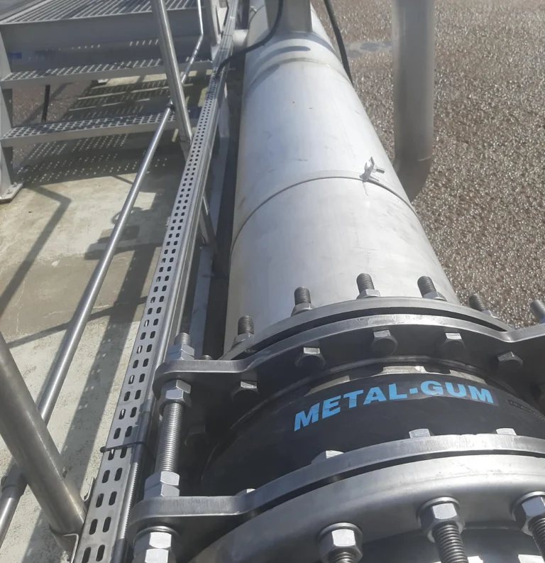
For rubber and PTFE expansion joints, send us the DN, medium, pressure, temperature, required movements and an installation diagram. This makes it possible to start the selection from the operating conditions of the installation rather than from the catalogue designation alone.