
RUBBER EXPANSION JOINTS
Rubber expansion jointsSelection for pipeline movements
Axial, lateral and angular movement in engineering practice
Rubber expansion joint selection should be based on the actual way the pipeline operates. DN and PN define connection and pressure conditions, but they do not describe the movements that the flexible element will accommodate during service. The direction and magnitude of movement, temperature, medium, pressure, installation conditions, and the way the pipeline is guided between anchors and guides are all relevant.
In practice, the same expansion joint can behave very differently in two installations with the same nominal diameter. The difference results from system geometry, pipe lengths, support arrangement and operating states. Selection should therefore relate the expansion joint parameters to the specific piping arrangement rather than only to connection data.
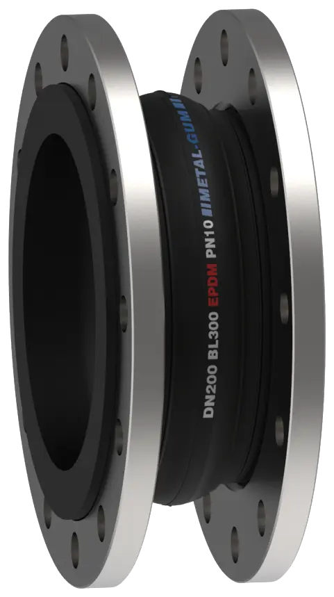
01 / MOVEMENT TYPES
Axial, lateral and angular movement
Selection starts with separating movements according to their direction. Axial, lateral and angular movement deform the bellows in different ways, so the actual value occurring in the installation should be defined for each of them.
Axial movement
Axial movement occurs along the pipeline axis and includes both compression and extension of the expansion joint. Values in both directions are required for selection. The total movement amplitude alone is not always sufficient, especially when the installed position does not correspond to the neutral position of the flexible element.
Lateral movement
Lateral movement means relative displacement between the axes of the two connections. If the movement occurs in more than one plane, the individual components and their directions should be defined. This is particularly important in three-dimensional systems where the expansion joint works together with several pipe sections and process equipment.
Angular movement
Angular movement is a change in the angle between the connection axes. The required deflection should result from the system geometry rather than from treating the maximum catalogue value as an available movement reserve.
Torsion about the axis
Twisting one connection relative to the other around the pipeline axis is not angular movement. It is a separate load case that should be identified independently. A rotating flange makes it easier to align bolt holes during installation, but it does not mean that the bellows is intended to accommodate torsion.
02 / COMBINED MOVEMENTS
Combined movements and use of the available movement range
In an actual installation, axial, lateral and angular movements may occur simultaneously. In that case, the maximum values for the individual movement directions should not be treated as independent ranges that can be used at the same time. Each deformation uses part of the bellows’ available movement capacity and affects the remaining range.
Assessing the system requires not only maximum values, but also the sequence of changes between operating states: after installation, after pipeline heating, under changing load, during shutdown or when process parameters change. This makes it possible to determine the extreme positions of the expansion joint and avoid a situation where the nominal movement range is available only in theory.
Pre-compression, pre-extension or offset of the expansion joint during installation also uses part of the available range. The installed position should therefore be considered together with the operating movements.
03 / PIPING SYSTEM
The expansion joint as part of the piping system
The operation of the expansion joint is directly related to the arrangement of anchors and guides. They define the direction in which individual pipe sections move and how movement is transferred to the flexible element. Pipe lengths and the positions of elbows, valves, pumps and other equipment connected to the system are also important.
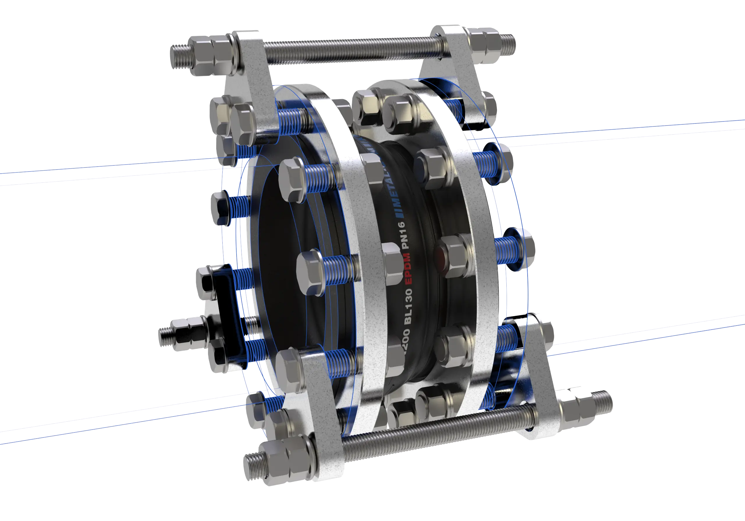
In pressurised installations, forces resulting from internal pressure must be taken into account. Their transmission should be provided for in the structural arrangement of the piping system. An expansion joint should not replace correctly designed anchors or carry loads that should be restrained by the installation structure.
Installation misalignment is a separate issue. Forcing pipeline alignment by permanently deforming the expansion joint changes its initial position and reduces the range available during operation. If the connection geometry requires correction, it should be considered separately from operating movements.
04 / CONNECTIONS
Rotating and non-rotating flanges
With a rotating flange, the bolt-hole position can be aligned with the mating flange during installation. The flange remains movable relative to the neck of the rubber element within the range needed to set the connection.

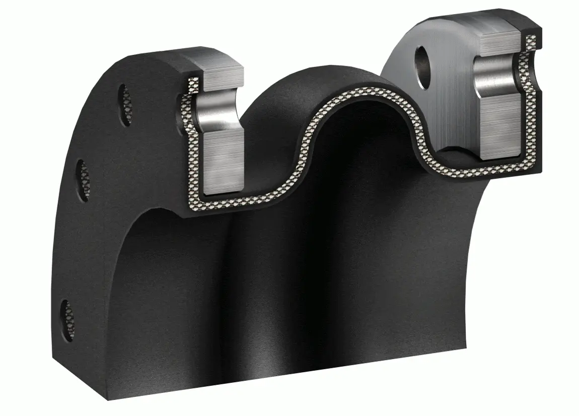
A non-rotating flange has a fixed position relative to the expansion joint and is used where the connection geometry or additional equipment requires a defined orientation. The flange type is a design feature of the connection and does not determine the direction of movement accommodated by the expansion joint.
05 / DESIGN GEOMETRY
Number of convolutions and design geometry
Single- and multi-convolution designs differ in the mechanical characteristics of the flexible element. Increasing the number of convolutions may change bellows flexibility and the available movement range, but it is not an independent indicator of allowable pressure, temperature or service life. Parameters must be related to the specific DN, geometry, material and operating conditions.
Reducer and conical designs are used where pipelines of different diameters are connected. In such cases, selection requires both nominal diameters, face-to-face length, reducer direction, medium parameters and the required movements. The characteristics of a standard cylindrical expansion joint should not automatically be transferred to a reducer design.
06 / SPECIAL CONDITIONS
Vacuum and additional equipment
Under vacuum conditions, the stability of the flexible element is important. Depending on diameter, expansion joint design, temperature and vacuum level, vacuum support rings or other solutions stabilising the bellows may be used.
Movement limiters are used to control the allowable extension or compression of the expansion joint. Their configuration should match the actual load path and work together with the anchor and guide arrangement.
A flow liner, also referred to as a deflector, protects the rubber element from direct exposure to the medium stream. It is used, among other cases, at elevated flow velocities, with abrasive media, or where protection of the inner bellows surface is important. Liner geometry and the required clearances must remain compatible with the intended movement range, particularly for lateral and angular movements.
External covers are used where the expansion joint is exposed to mechanical damage or adverse environmental conditions. Additional equipment should result from the operating conditions of the specific piping arrangement rather than from applying one standard set to every application.
07 / METAL-GUM RANGE
Metal-Gum rubber expansion joint range
Metal-Gum rubber expansion joints are manufactured in sizes up to DN3400, in nominal pressure classes PN6-PN25 and for operating temperatures up to +130 °C, depending on the elastomer compound and design. Available configurations include axial, multi-convolution, reducer and conical designs, as well as versions intended for vacuum service.
The operating range of a specific expansion joint depends on DN, flexible-element material, bellows geometry, pressure, temperature, medium and the required movements. Parameters should therefore be related to the relevant configuration rather than to the product family as a whole.
08 / SELECTION DATA
Data required for expansion joint selection
The more completely the piping arrangement is described, the more accurately the expansion joint can be selected. A technical enquiry should include:
- the medium, its composition and concentration if relevant to elastomer selection;
- operating temperature and the minimum and maximum values occurring in the installation;
- operating and maximum pressure, and the vacuum level if applicable;
- connection DN and PN, flange drilling standard and, if required, flange material;
- face-to-face length and available installation space;
- required axial compression and extension;
- lateral movements together with their directions or components;
- angular deflections and information on any torsion;
- the nature and number of operating cycles, if relevant to the application;
- the arrangement of anchors, guides and connected equipment.
For complex systems, it is useful to include an installation diagram showing anchors, guides, equipment, and movement directions and values. This makes it possible to assess relationships that cannot be described unambiguously by individual numerical values.
09 / RETROFIT
Replacing an expansion joint in an existing installation
When modernising an existing system, selection should not be based only on the designation of the old expansion joint. Installation photos, a drawing of the pipe section, the actual position of the component after shutdown, and information about previous operation help determine whether the previous expansion joint worked under the intended conditions.
Permanent offset, excessive extension, bellows collapse under vacuum, surface damage or traces of contact with internal elements may indicate a problem in the configuration of the complete piping arrangement. In that case, selecting a new component only from the dimensions of the old expansion joint may reproduce the previous operating condition and lead to similar damage.
10 / COMMON SELECTION ERRORS
Common selection errors
- Selecting only by DN and PN without defining the actual pipeline movements.
- Treating maximum axial, lateral and angular movements as independent ranges available simultaneously.
- Omitting vacuum conditions and their effect on bellows stability.
- Missing information about anchors and guides.
- Using the expansion joint to compensate for pipeline misalignment at the expense of the flexible element’s working range.
- Treating a rotating flange as permission for torsional operation of the expansion joint.
- Transferring parameters between designs with different geometry, number of convolutions or additional equipment.
11 / METAL-GUM SELECTION
Metal-Gum expansion joint selection
For a typical application, the basic data are the medium, temperature, pressure, DN, PN, face-to-face length and required movements. For installations with more complex geometry, a piping diagram should also be provided. This makes it possible to relate the expansion joint design to the actual way the system operates and select a configuration that accounts for movements, process conditions and additional equipment.
12 / FAQ
FAQ
Can one expansion joint accommodate axial, lateral and angular movement?
Yes, if the specific configuration has been selected for that combination of movements. Allowable values must be considered together rather than as three independent maxima.
Can axial, lateral and angular movements all be used at their maximum values at the same time?
Catalogue values should not be interpreted that way. For combined movements, their simultaneous occurrence and the total use of the flexible element’s working range must be assessed.
Does a rotating flange allow the expansion joint to operate in torsion?
No. Rotation refers to positioning the flange relative to the rubber element during installation. Torsion about the pipeline axis is a separate load case.
Does a greater number of convolutions always mean a larger movement range?
The number of convolutions affects the mechanical characteristics of the flexible element, but the operating range also depends on DN, geometry, material, pressure, temperature and the specific design.
Does vacuum affect expansion joint selection?
Yes. Vacuum level, temperature, DN and bellows geometry affect stability and may require an appropriate design or vacuum-support elements.